Camera Shutter Tester
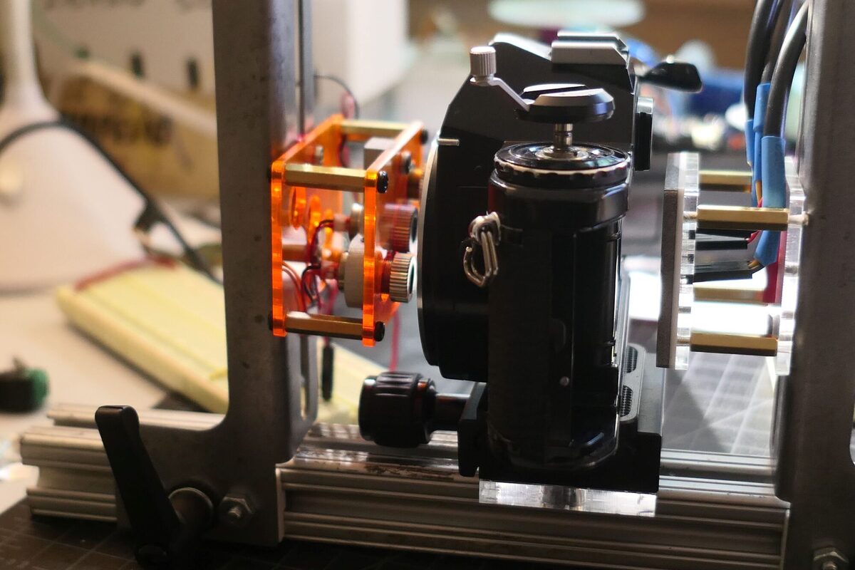
In order to any work on cameras, I needed a way to accurately test their shutter speed. I tried a cheap one that works with a phone, but the accuracy was highly suspect and it did not work at very high shutter speeds. If there are commericial ones I have not found them. Making my own proved to be a challenge, mainly because there is no way to know the readings you get from your tester are 100 percent accurate.
Like many diy shutter testers found on-line, I began with simple light and a phototransistor sensitive in the ambient light range.
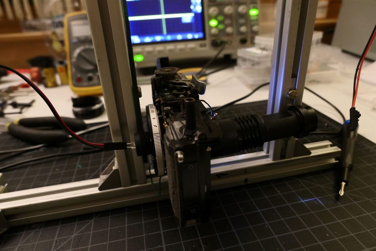
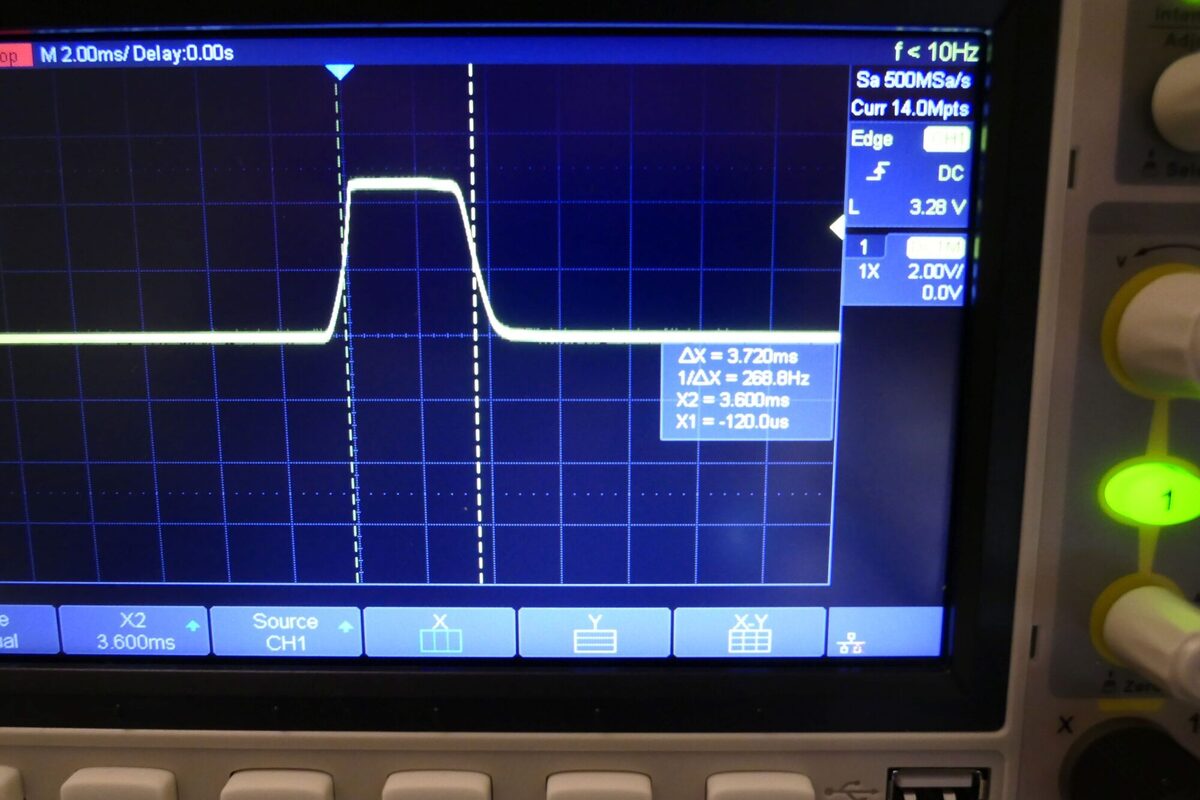
I read the output on a scope as shown below. There was no reason to suspect that this reading was incorrect or any reason to suspect is was completely accurate.
I honestly cannot remember all the interations I went through, but I landed on a design that uses three OPL560, an photodiode with integrated logic. The three sensors are placed in a diagonal line starting at the top left corner of the sensor plate and going down exactly 8mm and across 12mm.
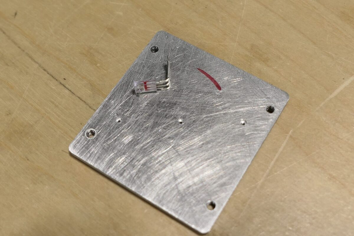
You can see the back of the sensor plate here. The holes are exactly .7mm in diameter and are counter sunk to allow the sensors to lay flat against the plate.
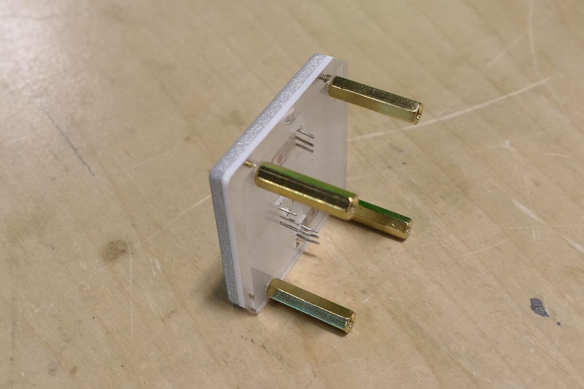
Below you can see the three-sensor module ready to be mounted.
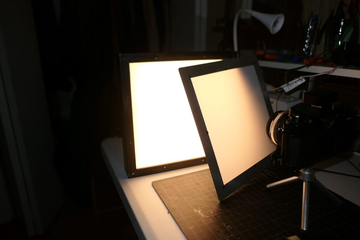
I did a lot of testing in this configuration. Originally, I used a 24V LED light panel that I made from a picture frame with custom magnetic filters. The light is bright–really bright. I measures over 16EV at 100ASA. I found that the sensors which have a wavelength of 935nm (high in the IR range) would only register when this light was on full–essentially it got hot enough to transmit IR light.
At the same time, I designed a circuit to display, shutter speed and curtain travel time. Using the scope was just getting too annoying. The circuit measures the shutter speed at each of the three sensors and the speed of both the front and rear curtain. The circuit takes advantage of the state machines inside of the RP2040 to capture everything independantly. I used the scope to confirm that the circuit is accurately reflecting the data from the sensors. The bigger question is: are the sensors accurately reflecting the data from the shutter!
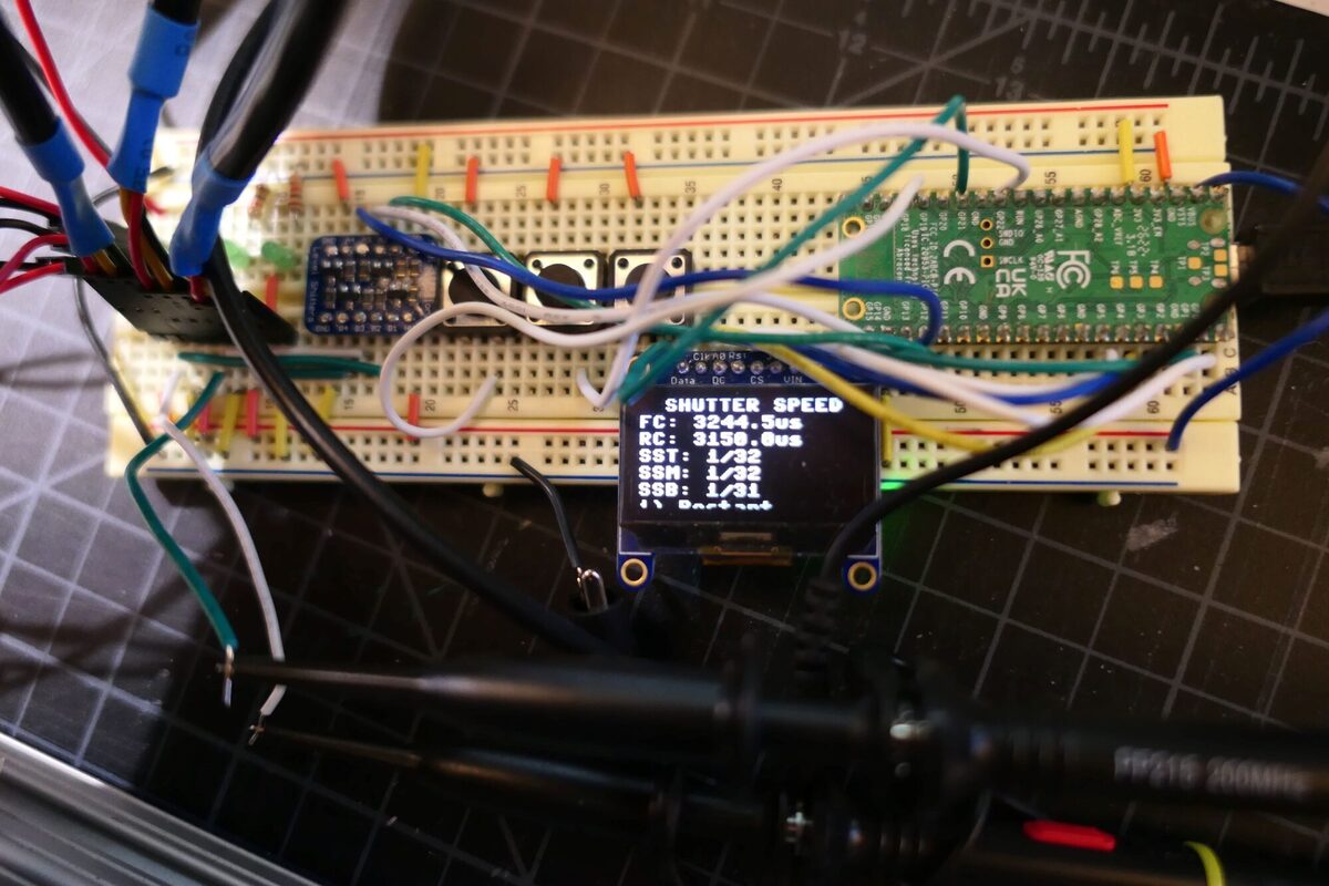
The above is taken from a Nikon FE2 in very good condition. The shutter speeds from each of the sensors are basically in agreement. The shutter travel time seems a bit faster than the expected 3.3ms noted in the Nikon repair manual. The circuit is able to captures speeds up to 1/4000. I don’t have a faster camera. The curtain travel times remain fairly consistent across all speeds, so that is something. I have not yet added any compenstation for the .7mm sensor gap which is more important at higher speeds.
My bigger concern has been getting consistent readings on all three sensors. One in the upper right corner of the shutter. One in the middle and one in the lower right. Initially there was a lot of variation, so I suspect diyers who have created shutter speed testers with a single sensor might be getting readings that are as accurate as they may think.
After realizing that pushing the brightness of the 24V LED panel just to squeeze out some IR light did not make sense. I then ordered a small IR panel that claimed to emit at 94nm.
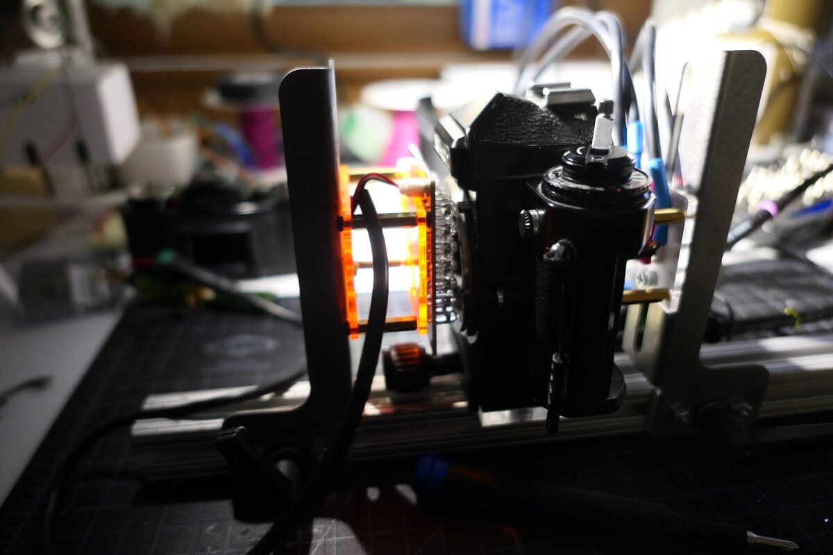
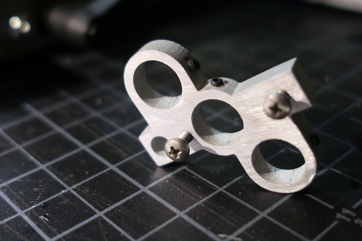
Though this panel never worked as well as I expected. I really needed to push it up against the camera to ensure it would trigger the sensors and the readings were not super consistent across the three sensors. I then decided to try IR diode lasers. Below you can see the triple laser mount that I machined with set screws to hold the lasers in place.
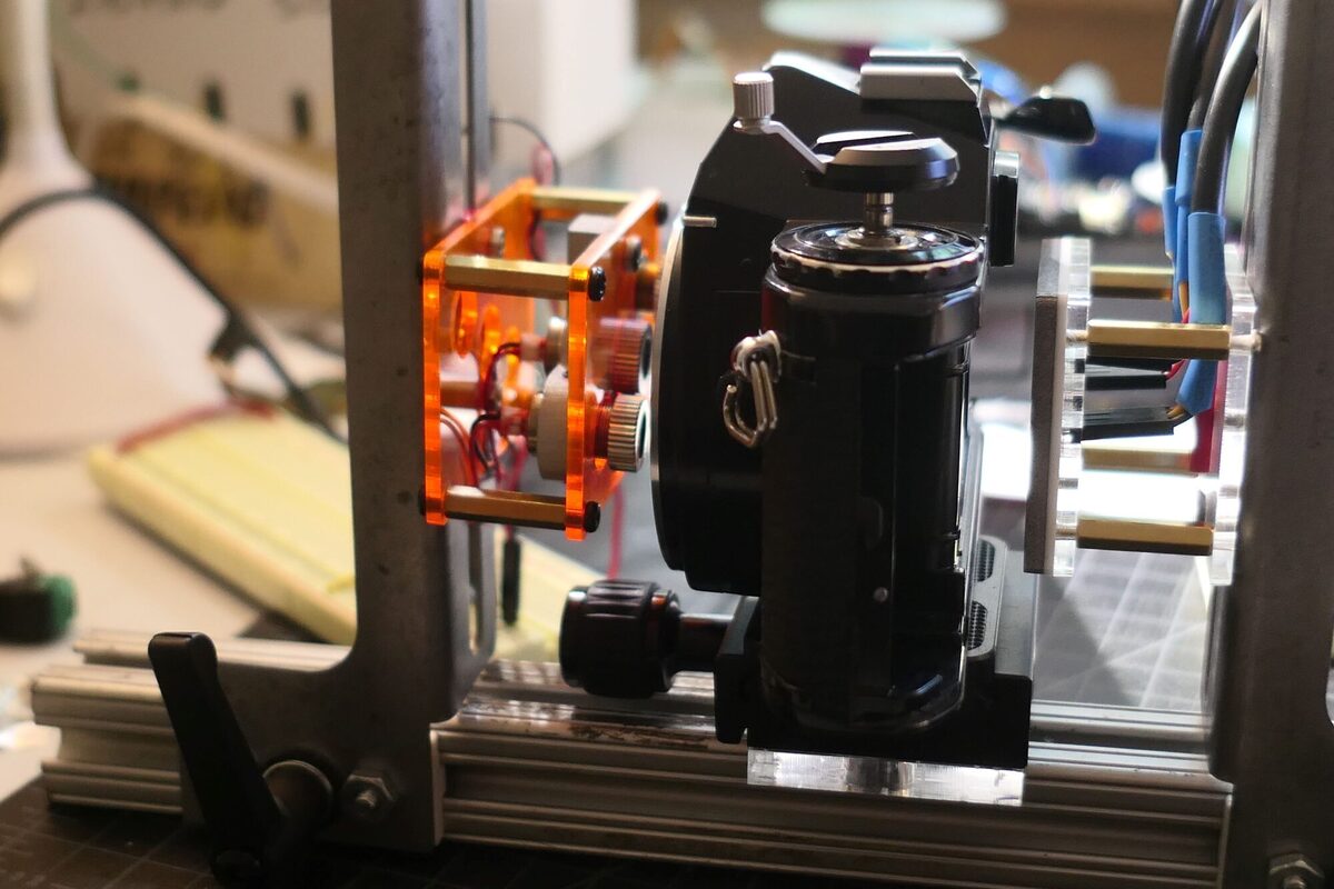
And here you can see the diode lasers in place.
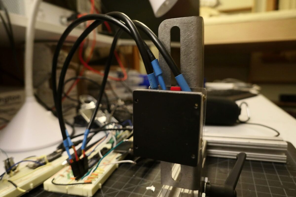
Using lasers the results improved a lot in that I was getting more consistent readings across all three sensors, but there were aberations and on the scope, and I noticed some pulses that I did not think should be there. It was then I realized that maybe using an aluminum plate (the result of realizing that earlier that IR light goes right through black acrylic, a whole other learning process) might be causing IR reflections. I finally painted the three sensor panel flat black as you can see below.
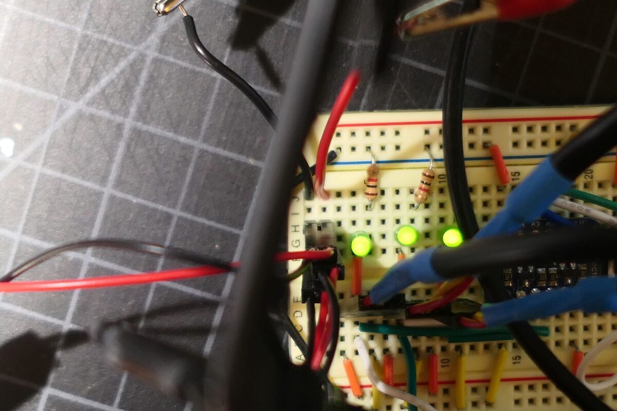
I also added three LEDs to the circuit which illuminate when a sensor is triggered. This way I am much more easily line up the lasers with the sensors through a camera using bulb mode. I also designed a PCB which puts the LEDs in the sensor plate and provides a 5-pin connector between the panel and the circuit. This would make everything much more compact.
This is where things stand. At this point I think the results are certainly good enough to adjust a camera’s shutter speeds to within an acceptable range. I still would really love a way to corroborate my findings and feel more confident with my readings.